

Slicing for large nozzles
Large-nozzle pellet printing behaves differently from small-nozzle filament work, especially once parts get wide, tall or heavy. This guide covers the settings that matter first so operators can tune for stable flow, usable surface finish and sensible print times.
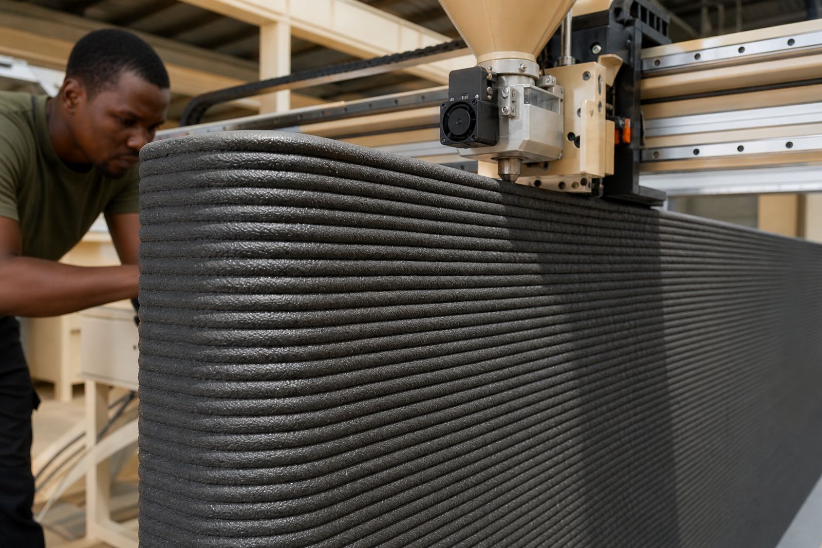
Start with flow, not fine detail
Large nozzles are chosen to move material quickly, so the slicer needs to be set around steady flow rather than tiny detail. On a pellet machine the screw extruder, melt zone and nozzle diameter all affect how much plastic can be pushed cleanly. If flow demand jumps too sharply, the bead can pulse, corners can overfill and top surfaces can look uneven.
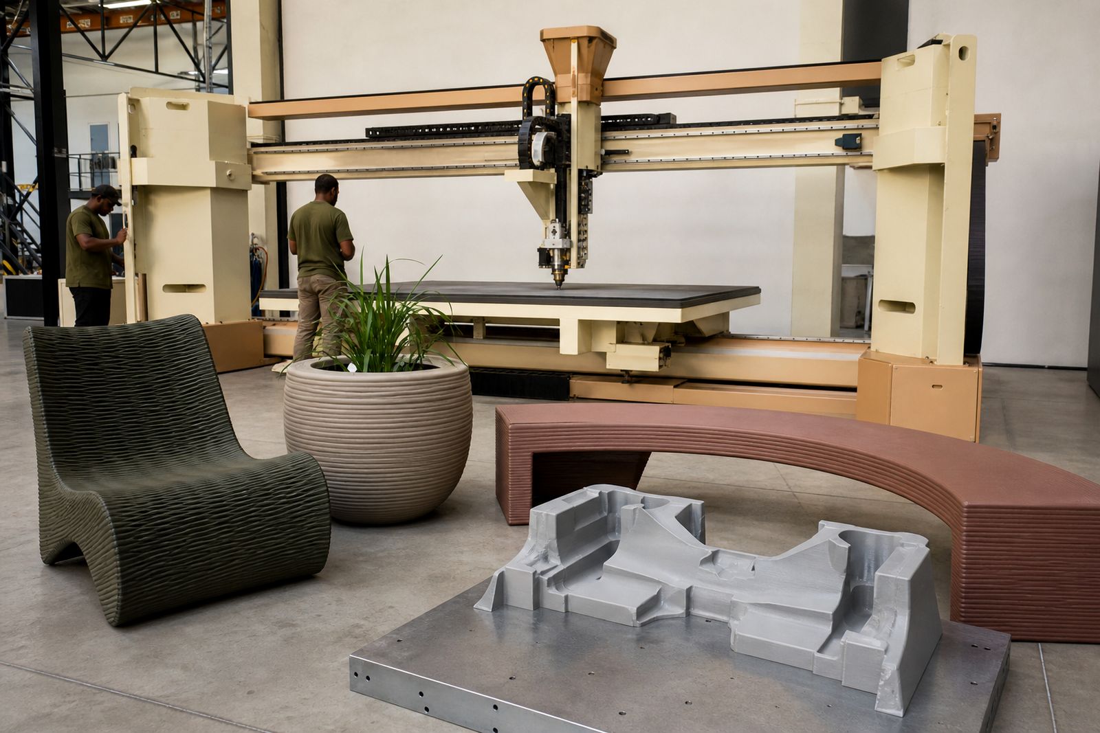
That is why the first pass should be conservative. Use a moderate line count, broad radii where possible and toolpaths that avoid constant stop-start motion. A chair shell, planter wall or mould backing plate usually prints better when the bead is kept consistent than when the file is forced into small decorative features it was never meant to hold.
- Match the slicing approach to the part’s job, not only its appearance.
- Begin with stable extrusion settings before chasing a smoother skin.
- Reduce abrupt speed changes on corners and short segments.
- Check that the model itself suits a large bead size.
Set bead width and layer height as a pair
Bead width and layer height should be treated together. A wide bead with a very low layer height can smear and drag, while a tall layer with too little width may not bond well at the edges. For pellet printing, a sensible starting point is usually a bead width that gives good side-to-side fusion and a layer height that lets the previous layer support the next one without slumping.
When operators only change one of these values, results often become confusing. A part may look strong in the middle but weak on the perimeter, or the nozzle may begin to brush against ridges on long straight runs. Adjust in small steps, print a short wall test and inspect bead shape from the side as well as from above. If the bead looks overly rounded, the layer may be too tall or flow too low. If it looks squashed flat, the nozzle may be too close, or the layer too thin for the bead.
- Use test coupons with straight walls and gentle corners.
- Inspect bonding between adjacent roads, not only outside finish.
- Watch for nozzle rubbing on ridges during travel and perimeter passes.
- Record successful width and height pairs for each material grade.
Balance print speed with melt capacity
Speed settings on pellet equipment are tied directly to how fast the extruder can melt and push material. A high travel speed on screen means very little if the melt rate cannot keep up. Under-fed lines often show as a bead that narrows unexpectedly, leaves gaps near corners or goes slightly matte where flow drops away.
It helps to think in terms of volumetric demand rather than only millimetres per second. Once bead width and layer height are chosen, each speed increase asks the extruder for more output. If the machine reaches its practical ceiling, back off before surface faults spread across a full-sized part. This matters on long furniture profiles and mould ribs where a weak section may only show up much later in trimming or assembly.
Cooling also plays a part. Some materials hold shape well at higher deposition rates, while others need slower passes or longer layer times to avoid sagging. In a warm workshop in Midrand, and even more so in coastal humidity, material behaviour can shift enough to justify a fresh test piece before a large run.
Choose toolpaths that suit big parts
Large-format jobs benefit from simple, deliberate toolpaths. Short zig-zags and frequent retractions are rarely ideal on pellet systems, because each interruption can leave a mark or build pressure variation in the nozzle. Perimeters, broad infill lanes and gradual direction changes usually give a cleaner result.
For benches, tables, mould blocks and display forms, think about where seams will sit and how the bead will stack over time. Place starts and stops away from cosmetic faces where possible. If the slicer allows different wall strategies, compare a few small sections rather than assuming the default pattern is best. A wall mode that looks efficient on screen can print badly if it forces the head into tight, repeated changes of pace.
- Keep seams off show faces where the part layout allows it.
- Prefer smoother path transitions over many tiny segments.
- Use infill patterns that support top surfaces without violent direction changes.
- Check travel moves for possible collisions on tall edges and curled corners.
Material condition changes the slice outcome
Good slicing cannot rescue wet or inconsistent pellets. Moisture in PLA, PETG, ABS, PP or fibre-filled grades can show up as bubbles, rough bead texture and weak bonding, even when the slicer looks sensible. Drying and feed consistency should be checked before major slicing changes are made.
Different pellet grades also respond differently to the same nozzle and speed plan. Fibre-filled compounds may prefer lower speeds or altered bead overlap to keep edges tidy. More flexible grades can need slighly gentler acceleration so the bead lands cleanly instead of wandering on corners. Regrind content adds another variable, especially where pellet size distribution is mixed and feed behaviour changes through a long print.
When a profile works on one material, save it with clear notes. Operators waste time when proven settings are remembered loosely instead of being logged with the pellet type, drying condition and nozzle setup used that day.
A practical setup checklist before full production
Before committing to a full chair, mould section or architectural piece, run a short validation routine. The aim is not to perfect every surface, it is to confirm that the slicer, material and machine are aligned well enough for a long print to finish without avoidable faults. This small step usually saves far more time than it costs.
- Print a wall sample to confirm bead shape and layer bonding.
- Measure actual wall thickness against the sliced value.
- Inspect corners for overfill, gaps or pressure lag.
- Check top layers for bridging quality and heat build-up.
- Confirm the nozzle clears previous layers on travel and perimeter passes.
- Review seam placement on the visible faces of the part.
- Make sure the pellet feed stays consistent through the test.
- Log the final profile name so the same settings are used on the production file.
If a part will be machined after printing, include that in the slicing plan. Extra skin thickness, altered wall count or a different top-surface strategy can make trimming and finishing much easier in the workshop.
What our Pellet 3D Printing customers say
Verified Google reviews
Questions we get asked
Can I use normal filament slicer settings on a pellet printer?
Only as a rough starting point. Pellet systems usually need different assumptions for bead width, acceleration, flow stability and seam handling, especially on large parts.
Why do my corners bulge with a large nozzle?
Corners often bulge when the machine carries too much pressure into a slowdown or direction change. Lowering print speed, softening acceleration and revising bead width can help.
Does a larger nozzle always mean faster printing?
Not automatically. A larger nozzle can move more material, but the real limit is the machine’s melt capacity, the material’s cooling behaviour and how the part is sliced.
Also worth a look
Tell us about the job
Send sizes, materials and where you are through our contact form, and we will come back with the practical options.
Open the contact form